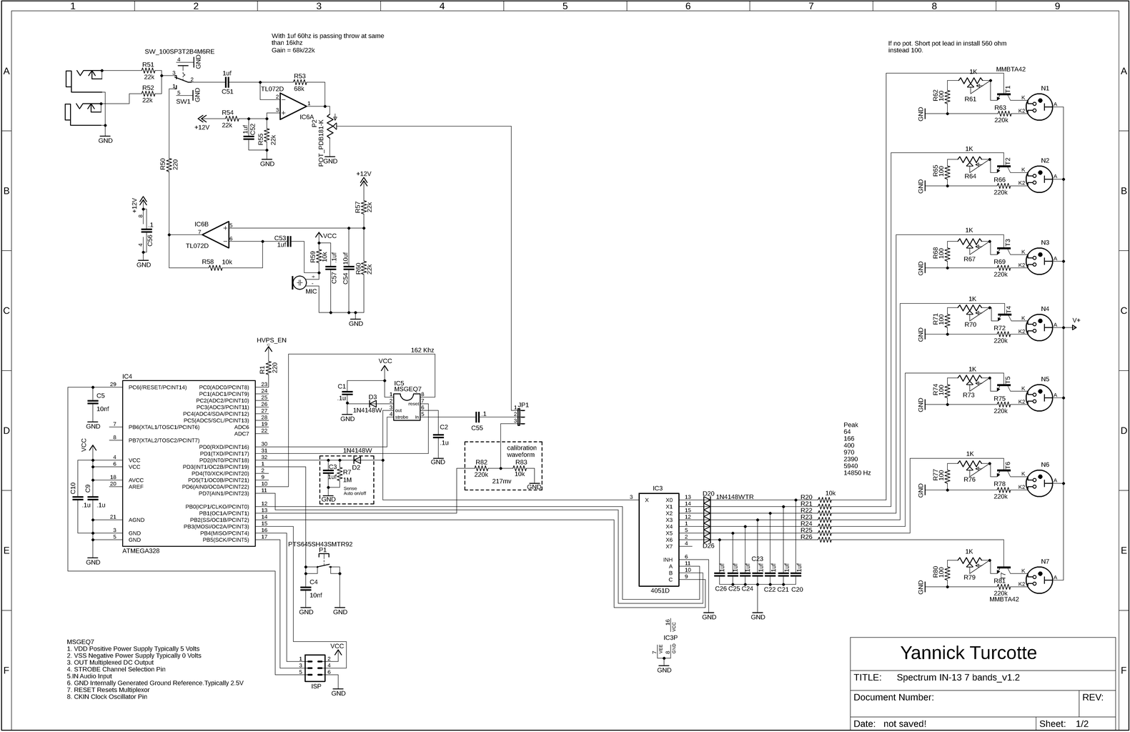
Spectrumanalyzer fr Audio selbst bauen Circuit Diagram Run an audio signal through it and you have an instant audio spectrum analyzer! This is a simple spectrum analyzer based on an Arduino. Each of the 5 LEDs represent a single section of the chip's 7 sections of audio spectrum. Hi, I am trying to build this circuit. I have checked my wiring and connections and for some reason the lights don If we add an AGC/ALC circuit with the Audio Spectrum Analyzer circuit, the LED display can work irrespective of amplifiers volume control setting. Eg:- If I take audio input from speaker terminals (such cases when a preamplifier output is not accessable), the displays beauty will lose when we increase and decrease amplifiers volume. In an audio signal, frequency is pitch. That means that higher frequency ranges correspond to higher notes in the audio. This spectrum analyzer utilizes an MSGEQ7 IC, which is an equalizer filter, to pull seven frequency ranges from an audio signal. It outputs the peak of each band, giving a real-time reading of each band's amplitude.
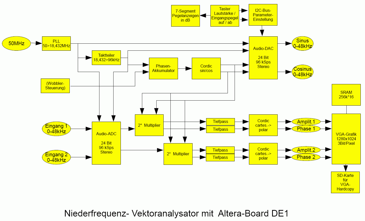
A spectrum analyzer measures the magnitude of an input signal versus frequency within the full frequency range of the instrument. In this project is presented a very simple way in which such a device can be made with the help of only a few components: - Arduino Nano microcontroller - 16X2 LCD display - capacitor 47 nF and
DIY Spectrum Analyzer: Building Your Audio Tool Circuit Diagram
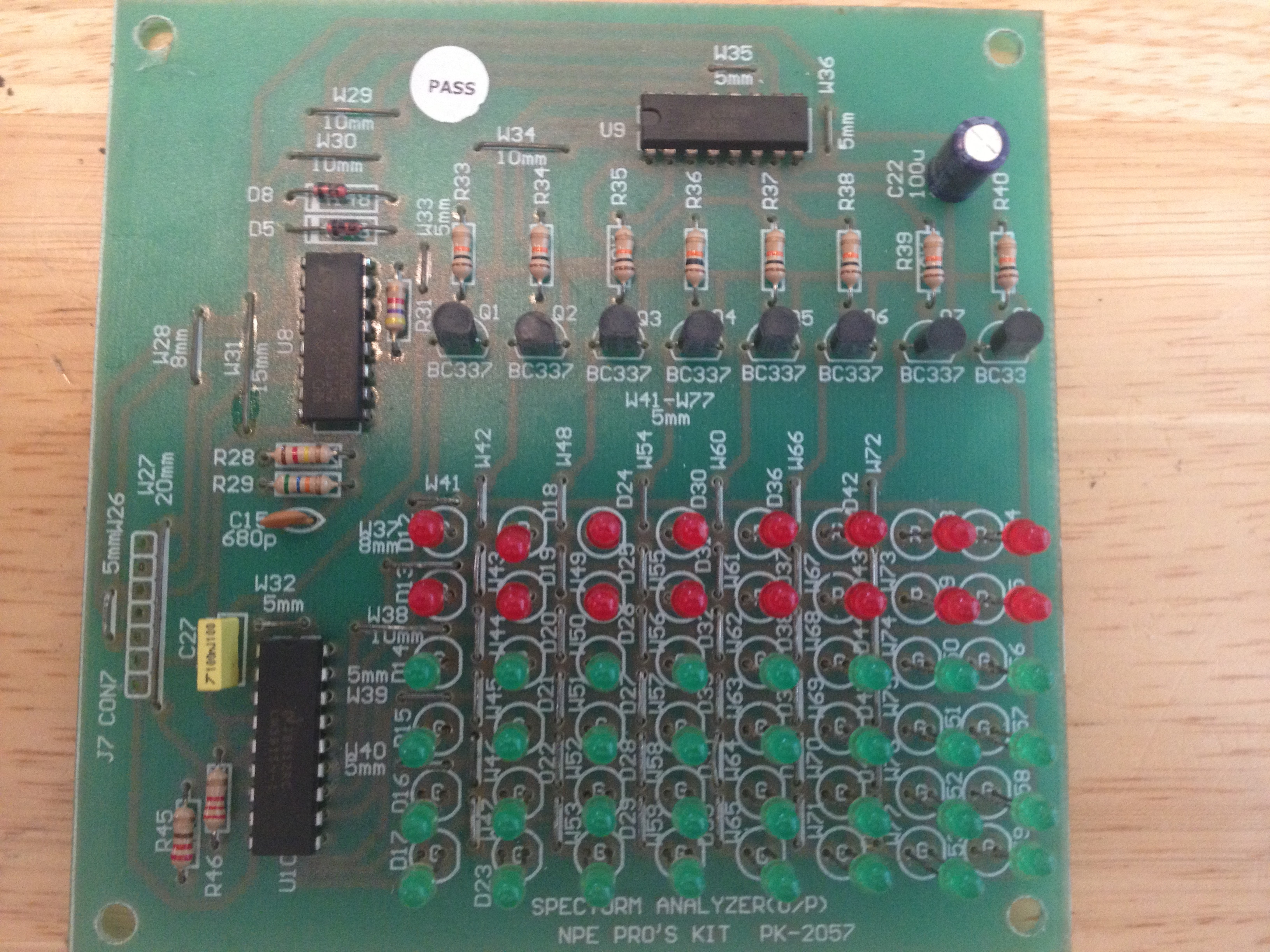
A voltage divider circuit is used to provide a reference voltage (1V, 2V, 3V and 4V) to each op-amp. (-) pin of all the op-amps are connected together. As the voltage at (-) pin becomes greater than 1V, the output of the first op-amp becomes high. Using the same principle but with more op-amps, we can build an Audio Spectrum Analyzer since The 9 DIY Steps for Developing a Spectrum Analyzer. Step 1: Start by soldering all the LEDs to one side of the PCB.Remember that there are 50 pieces of different colored LEDs to be soldered. The task here is to solder LEDs with similar colors on one side or column of the PCB and do the same for the others.
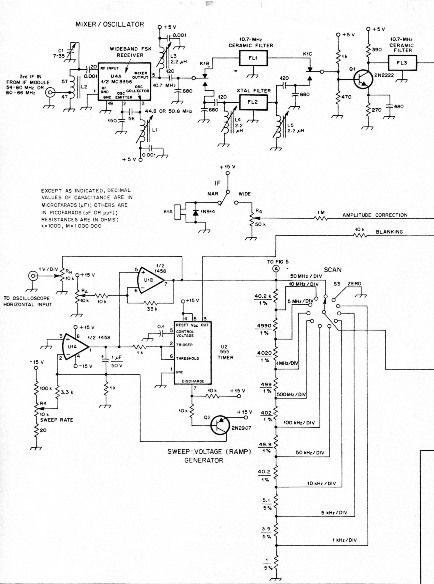
[Ryan] wanted a spectrum analyzer for his audio equipment. Rather than grab a micro, he did it the analog way. [Ryan] designed a 10 band audio spectrum analyzer. This means that he needs 10 band
Audio Spectrum Analyzer Circuit Diagram
To create a DIY Spectrum Analyzer, important components include a circuit board and display options. Investing in quality components is paramount for accurate performance. Understanding the importance of a Spectrum Analyzer in audio work is crucial, as it allows for precise analysis and optimization of audio signals.
