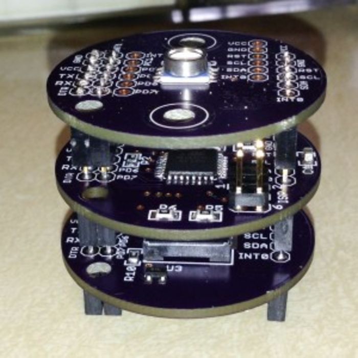
SparkFun DataLogger IoT Environmental Kit Circuit Diagram Making ESP32 IoT Decibel Meter (SPL) with Data Logger. Now we have tested the Decibel Meter and read the values on Serail monitor, we can further enhance this project. We can use a 0.96″ I2C OLED Display for real-time reading of dB SPL value. We can also send the value to any IoT platform such as Blynk, Thingspeak, Ubidots or any other Server. At this point go back to the cloud platform, copy the contents of the .ino file: The .ino file. and paste it into the main.cpp file of the PlatformIO project, in order to completely replace its contents.. Now create in the include folder a file that you will call thingProperties.h, go to the cloud platform, copy the content of the tab thingProperties.h: This tutorial will show step by step construction of that basic plan using the more common Sparkfun pro-mini style Arduino board, which has different pin locations than the Rocket Ultra but the connections are all the same. We will be assembling the logger on a plumbing test cap platform to facilitate placement in a 4″ housing made from plumbing parts:

In this 8-part series, we'll go through the practical skills and knowledge base you need to deploy a custom, Arduino-based data logger in the field. Through 6.5 hours of instructional, learn-at-your-own-pace videos, Office Hour events, and resources, we cover everything a beginner to Arduino needs to get started, from common terminology and components to programming, Hackster.io — Hackster.io offers a development community for learning and building an IoT project. You can take inspiration from the thousands of IoT projects that are listed on their website. Adafruit — Adafruit is the go-to place to learn anything about building IoT projects. They offer tons of resources, hardware, and guides to help you

Design and fabrication of a low cost data logger for solar energy ... Circuit Diagram
Use the shortcut CTRL + C or CMD + C to copy this data. Save that file as a .txt file. It's ready for the next step! As for your device, if you wish to erase that trip's data from its memory, send '2' to clear all data: Make sure you've saved all your data before taking this action! Now we get to the best part - visualizing your GPS data!

Use the shortcut CTRL + C or CMD + C to copy this data. Save that file as a .txt file. It's ready for the next step! As for your device, if you wish to erase that trip's data from its memory, send '2' to clear all data: Make sure you've saved all your data before taking this action! Now we get to the best part - visualizing your GPS data! Next, solder the 10K resistors between the 3V rail next to the proto space and the two holes shown in the images. They will be linking the SCL and SDA pins on the sensor to the 3V rail as the pull-up on each pin. To verify you're connecting the right spots, place your sensor through the holes on the end of the Feather proto area, and make sure that you're placing one end of the resistors on
