Infrared IR Transmitter and Receiver Circuit Circuit Diagram You will be setting up two separate circuits both using an Arduino. The first example circuit uses a TSOP382 IR photo sensor to receive and demodulate the IR signal from a common remote control. The second example circuit uses a 950nm IR LED and current limiting resistor to transmit IR codes to a common appliance, for example a home stereo or TV.

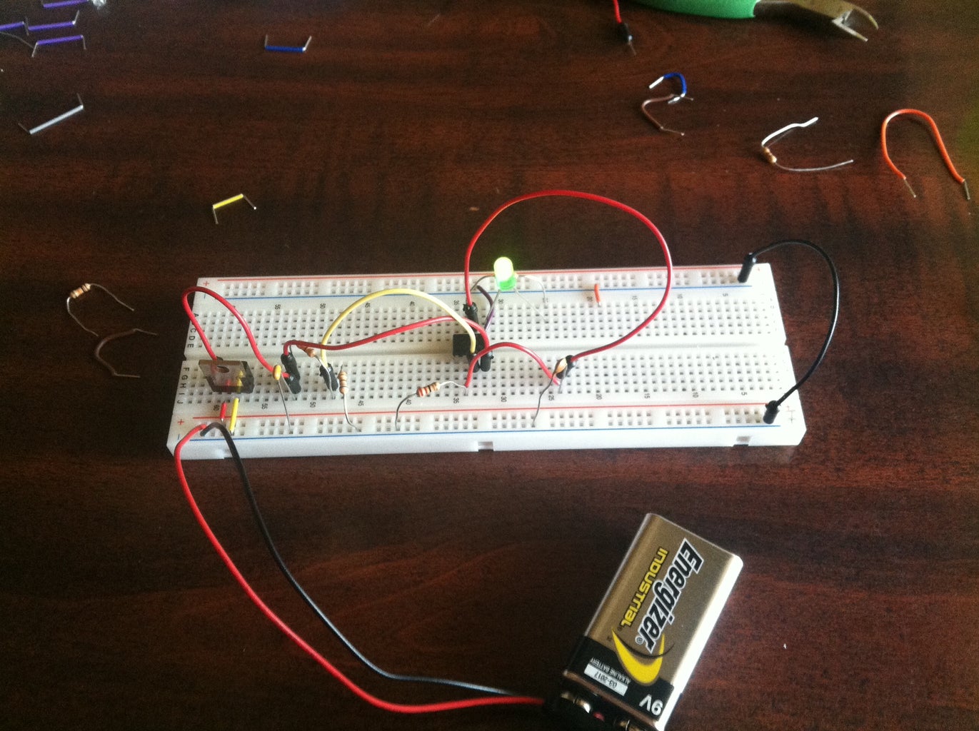
IR LED's are commonly used in conjunction with the IR receiver to support a wireless communication between 2 or more devices. Step 3: 2. IR Receiver [PhotoDiode] Basically, an IR Module is a combination of a IR transmitter and receiver circuit. Infrared light emitted by the IR LED is detected by the Photodiode. LM358 Op-Amp IC is used The optical transmitter circuit makes use of an LED to generate an AF controlled, infrared or visible stream of light which can be recognized by the phototransistor inside the receiver circuit. This phototransistor needs to have a peak sensitivity at the LED's peak emission wavelength in case the best possible efficiency is required. Before you finish the circuit, make sure the IR LED and Photodiode are placed next to each other. Once the circuit is complete, test the sensor by hovering an object or your finger about 5cm above the two diodes, then slowly move the object/finger towards the diodes till you touch them both. The generic LED should light up more the closer you
Visible Light Communication Circuit [using InfraRed] Circuit Diagram
Ensure that the IR LED is aligned in a manner that facilitates effective transmission of infrared signals to the targeted electronic appliances, maximizing the range and accuracy of the IR blaster. With the circuit and IR LED seamlessly integrated into the enclosure, proceed to secure the components in place.
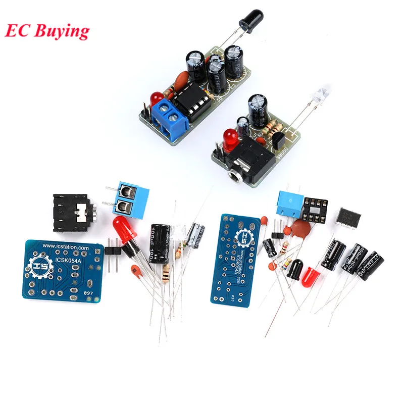
The Arduino UNO reads the state of three buttons. When a button is pressed, the Arduino uses the IRremote library to transmit a unique hexadecimal code encoded as an IR signal through the IR LED. Different codes can be assigned to each button press, allowing for communication of specific instructions to an IR receiver. Parts List. Arduino; IR

Infrared IR Transmitter and Receiver Circuit Circuit Diagram
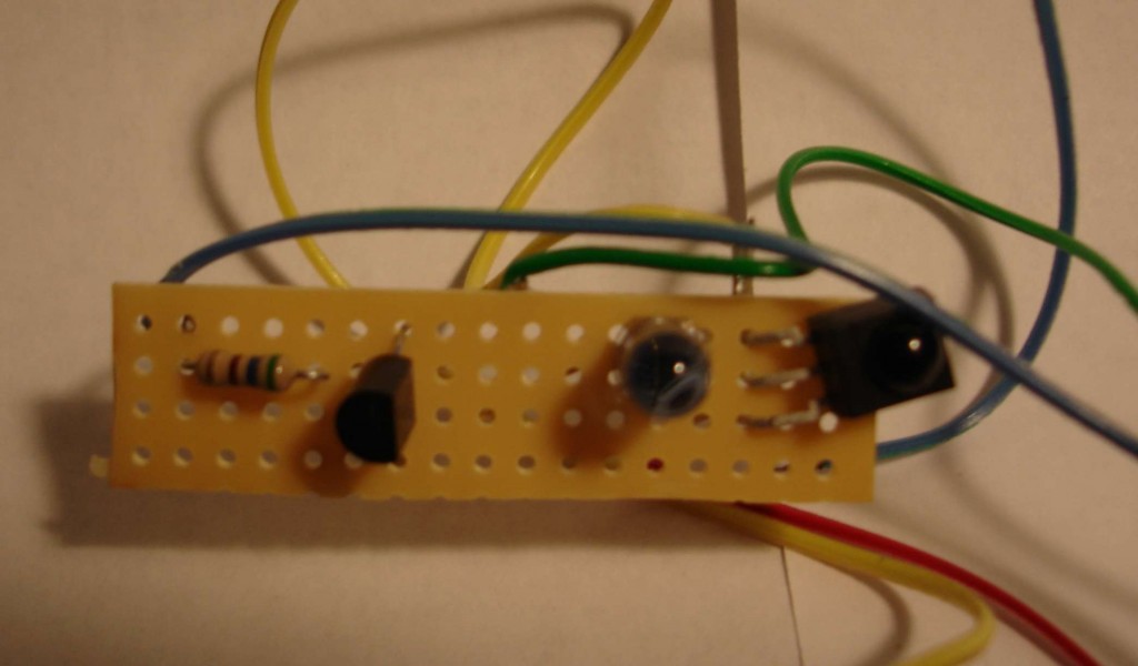
control circuit however the 38238 from Adafruit will work fine under most every circumstance. You may also need an infrared learner device the TSMP 58000 from Digi-Key. We will explain later why you might need a TSMP58000. IR (Infrared) Receiver Sensor IR sensor tuned to 38KHz, perfect for receiving commands from a TV remote control. Step-by-Step Guide to Building the Infrared Jammer Circuit. Assemble the Components: Place all components on a breadboard or solder them onto a perf board for a more permanent setup. Building an infrared jammer circuit is a great way to understand IR communication and how it can be disrupted. This simple yet effective project demonstrates An IR transmitter and receiver pair form a simple circuit. This project explains the principle of IR communication. The 555 Timer IC operates in an astable mode. It generates continuous pulses of the frequency. As the switch is pressed, the connection between an IR LED and the 555 timer IC closes. Then the IR LED emits light of some frequency.

Tv ir remote uses InfraRed NEC Protocol for communication between infraRed remote and Tv itself. So I am going to make ir transmitter and Receiver using NEC Protocol that can be used for various purposes. Like controlling Appliances or Making IR Shark which would be a great Fun and easy to hack IR remotes.