How to Build a Simple Function Generator Circuit with an LM324 Op Amp Circuit Diagram Today we will be using the ICL8038 voltage-controlled oscillator, or precision waveform generator, to create four function generator circuits. The ICL8038 can generate three output waveforms without many external components: a sine wave, a triangular wave, and a square wave.

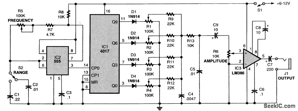
My circuit is designed to generate signals up to 100 Kilo-hertz.Lets learn how to build a crude signal generator with variable frequency, amplitude and duty cycle. This circuit is built around the waveform function generator IC 8038 capable of generating frequencies up to 300 KHz. My circuit is designed to generate signals up to 100 Kilo-hertz.
DIY Arduino Waveform Generator or Function Generator Circuit Diagram
1) Using IC 4049. Using only one low-cost CMOS IC 4049 and a handful of separate modules, it is easy to create a robust function generator that will provide a range of three waveforms around and beyond the audio spectrum.. The purpose of the article was to create a basic, cost-effective, open source frequency generator that is easy to construct and used by all hobbyists and lab professionals. The below indicated sine wave generator circuit is not only easy to build, it also provides an exceptionally pure output having a total noise and distortion level that is effectively under 0.1%. The design is a simple Wien Bridge oscillator configured around an operational amplifier.
This function generator a.k.a waveform generator can produce square wave (5V/0V) with frequency ranging from 1Hz to 2MHz, the frequency of the wave can be controlled by a knob and the duty cycle is hardcoded to 50% but it is easy to change that in the program as well. Apart from that, the generator can also produce since wave with frequency
How to Build Your Own Function Generator Using Analog Devices' AD9833 Circuit Diagram
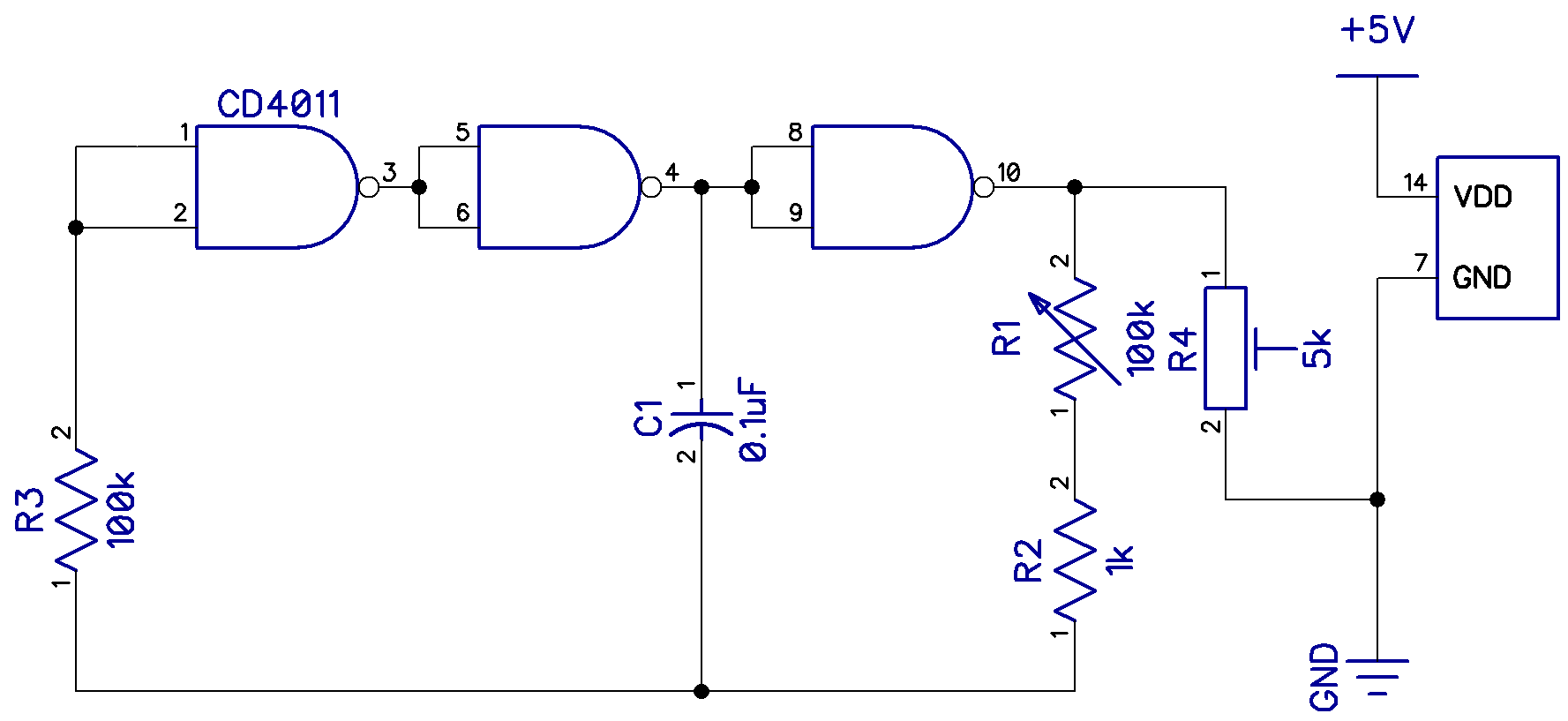
DIY Function/Waveform Generator: In this project we will have a short look at commercial function/waveform generators in order to determine what features are important for a DIY version. Afterwards I will then show you how to create a simple function generator, the analog and digital way. Step 3: Build the Circuit! Here you can find the This simple waveform generator circuit consists of a single TTL 74LS14 Schmitt inverter logic gate with a capacitor, C connected between its input terminal and ground, ( 0v ) and the positive feedback required for the circuit to oscillate being provided by the feedback resistor, R. So how does it work?. Assume that the charge across the capacitors plates is below the Schmitt's lower DAC Schematic Design for an Arbitrary Waveform Generator. DAC Output Circuitry for an Arbitrary Waveform Generator. PCB Layout for an Arbitrary Waveform Generator. How to Generate a High-Precision Waveform Using a DAC and a Custom PCB. High-Speed Waveform Generation with an MCU and a DAC. Having your own electronics laboratory at home is great
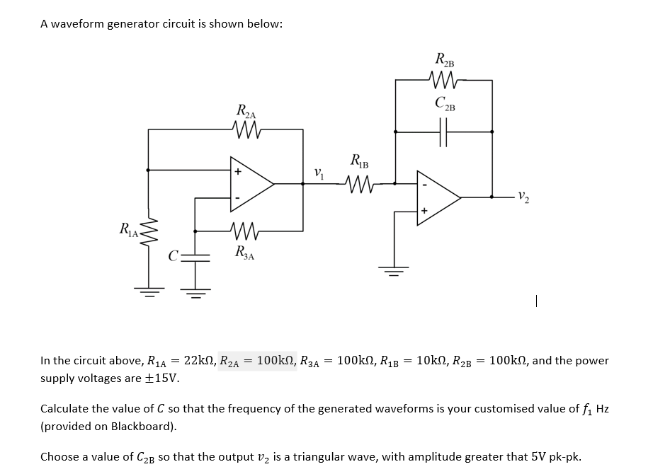
The bridge circuit is C1 R4a and C3 R4b. R4 is a dual-ganged potentiometer and controls the frequency, which is 1/2πRC. Assuming R4 is central, say 2k, this would be 1/(2*π* 5k * 0.01u) = 3kHz. The lamp is a small 12V incandescent light bulb.As the filament heats up, its resistance goes up, reducing the current through it, reducing the gain and amplitude at the output, so you have a very I made a simple waveform generator using operational amplifier, here this signal generator can be used to verify the electronics circuits and small integrated circuits. It can generate square wave and triangular wave up to 5khz. The main reason to make this type of waveform generator is price, it can be made under $2. And requires very few
