Home Alarm system Circuit Diagram In this video we'll discuss the basics of putting together an alarm system for your home or business. Back to Main Hi, I'm Jason with alarmsystemstore.com, and in today's video, I'm gonna talk about the basics in alarm system design. We'll start with the first layer of defense, door and window contacts. These should be • Article 700: Emergency Systems (Legally Required), 700.28 Coordination • Article 701: Legally Required Standby Systems, 701.27 Coordination • Article 708: Critical Operations Power Systems, 708.54 Coordination 1 10 100 1K 10K 100K 0.0 1 0.1 0 1 10 1 00 100 0 CURRENT IN AMPERES Curve 5.tcc Ref. Voltage: 480 Current Scale x10^0 T I M E IN Hi sorry dont have schematic. but let me try to explain. the existing circuit is from an existing alarm system that does not have a buzzer. The Alarm system cannot be altered or tampered with so not much room there. This is a 40 year old circuit. The alarm currently has 8 outputs in the form of 24V lamps. The whole system runs on 24V (we are

2- Fire alarm system 3- Telephone system 4- CCTV system. HVAC system. Make a Load Schedule Calculations Using Excel. Generator Sizing manually and Using Cummins software. Make UPS Sizing. Design a Single Line Diagram with ETAP. Make S.C (Short Circuit) calculations for any electrical system with ETAP. Make the Voltage Drop calculations for any Basic foundational training in the four core competencies of low voltage systems: Intrusion Systems; Video Security Systems; Access Control Systems; Fire Alarm Systems; This training focuses on getting your new employees up to speed as quickly as possible in design considerations for these systems and code compliance.
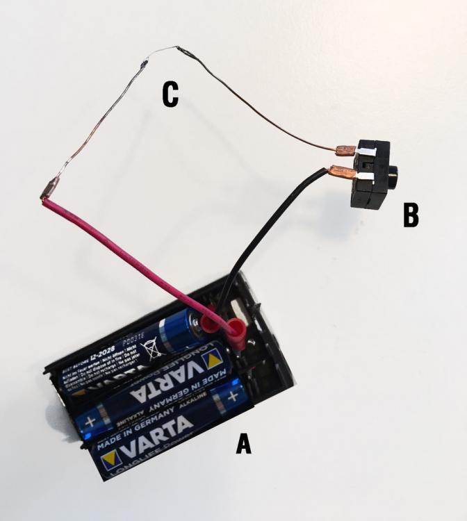
Need a simple alarm (buzzer) that is triggered when the voltage drops ... Circuit Diagram
To create a basic fire alarm system that uses an IR fire detector sensor to detect fire and activate a buzzer powered by a 9V battery. Materials Needed: IR Fire Detector Sensor (Infrared flame sensor) Buzzer (9V or low-power buzzer) 9V Battery and battery clip; NPN Transistor (e.g., BC547 or 2N2222) Resistors (1kΩ for the transistor base)
Components Needed for a Basic Alarm Circuit. An alarm circuit is a simple electronic device used to detect and alert you to the presence of an intruder or a dangerous situation. It typically consists of several components working together to create a basic alarm system. Here are the key components needed for a basic alarm circuit: 1. Sensor
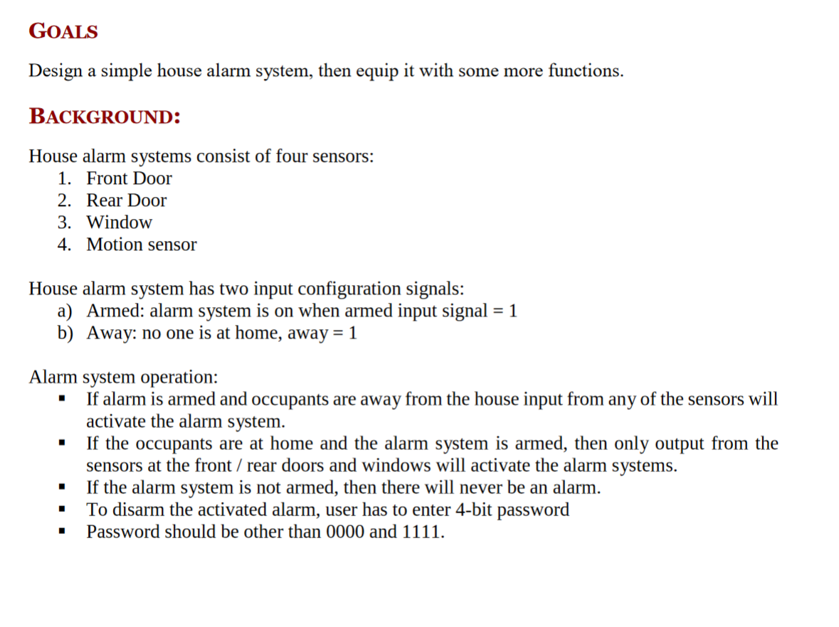
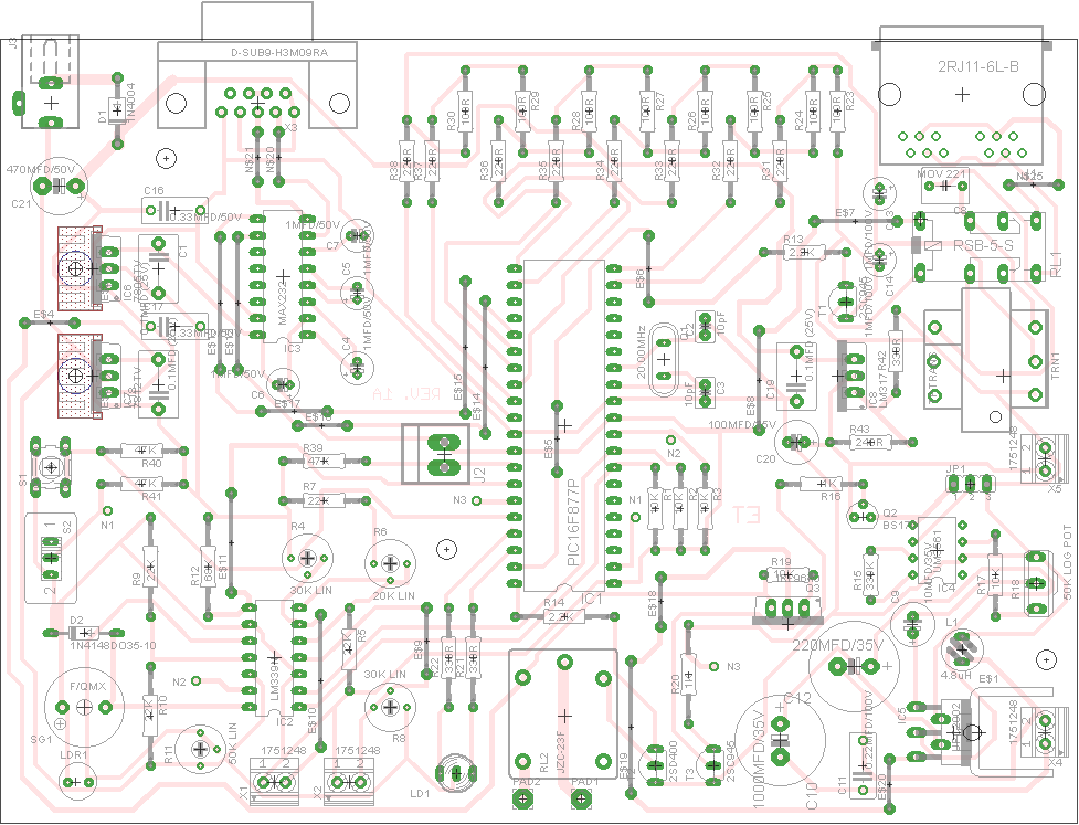
How to design an alarm system Circuit Diagram
The NTC Blue Book is the authority on low voltage systems. The fire alarm section covers the basic code requirements for fire alarm systems and how to actually employ them in real life jobs. The access control section focuses on how to design access control systems to meet the need of your customers.