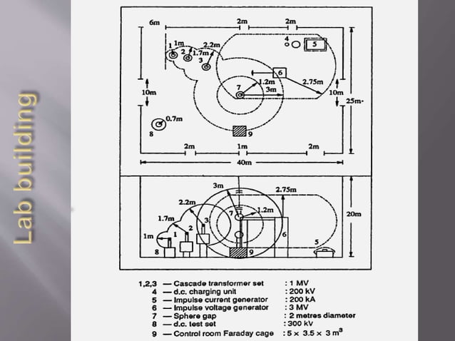
Highvoltage experimental setup Circuit Diagram High voltage PCB operates at greater voltages than the typical rail voltage. Mains-powered power supply, Inverters, and EV chargers are examples of this type of board. High voltage does not have a predetermined threshold. A good starting point would be 100 volts for printed circuit boards—this is the normal range of voltage. However, over 100 volts need extra considerations that you would Compliance and Safety Standards for High Voltage Circuit Boards. High voltage circuit boards (HVPCBs) must adhere to specific design and safety standards to ensure their reliability and safe operation. One of the most critical standards is IPC-2221, which outlines design principles for creepage and clearance distances. Working within high-voltage circuit boxes becomes easier when you design them properly. High-voltage semiconductor devices used for motor control circuits and power supplies include MOSFETs, Insulated Gate Bipolar Transistors, MOS-controlled Thyristors, Power FETs, and Silicon-Controlled Rectifiers. PCB design rules must follow manufacturer

High voltage board designing requires an understanding of international safety standards such as IPC 2221A and UL 60950-1. In this article, you will be learning some critical considerations important from a high voltage PCB design angle. Creepage and clearance considerations in high voltage circuit boards Designed to protect sensitive electronic components from ESD. Intended to protect circuits from high-voltage, short-duration static events. Built to protect against transient voltage spikes (high-energy voltage surges) caused by events like lightning strikes, power line crosses, or switching events in electrical circuits. Techniques For Effective High Voltage PCB Layout. Designing a high voltage printed circuit board (PCB) requires meticulous attention to detail and adherence to specific guidelines to ensure safety, reliability, and performance. One of the primary considerations in high voltage PCB design is the spacing between conductive elements.

High Voltage PCB Design: Material Selection, Guidelines, and Safety ... Circuit Diagram
Disadvantages of High Voltage PCB Design. Some of the main drawbacks of high voltage printed circuit board design include: ·Time-consuming. The fabrication and assembly of high voltage PCBs are time-consuming. This is due to the additional modifications required, including the use of heavier copper unlike in the other PCBs. ·Expensive By following these design principles and best practices, engineers can produce high-voltage PCBs that operate efficiently and safely in demanding applications. Turn-times as fast as one day. FS Circuits can manufacture your PCB and have it expedited to you within 24 hours.

High Voltage PCB Design Tips: Materials for High Voltage PCBs. HIGH-VOLTAGE PCB DESIGN www.altium.com HOW TO PLAN YOUR PCB LAYOUT FOR A HIGH VOLTAGE DESIGN I used to trail run with a friend who is an urban planner. As part of her devious plan to get me to run further before I was too tired enough and I needed to change the BUCK design that Routing and Trace Design. Routing is the path that electrical signals follow on the PCB. It is especially important with high-voltage circuits. Increase Trace Width: Wider traces can carry more current and generate less heat.They also reduce resistance. Spacing is Key: Keep enough distance between traces to prevent arcing.; Avoid Sharp Corners: Use smooth curves instead of 90-degree angles.
