Circuit Diagram For Dual Power Supply A dual power supply circuit is a great option for applications that require two power sources. It simplifies the design of the circuit and allows for greater flexibility. In this article, we've explained how to build a dual power supply circuit, from gathering the components to switching between the two power sources. History of design - For another project I'm working on, I needed a dimensionally small power supply of voltage -+12V and a current of at least 1A. I already had small experience with the LM2596 circuit, so I used its 12V version here. I don't think anyone will need to make PCB as I designed it, because my PCB is designed as a part of another

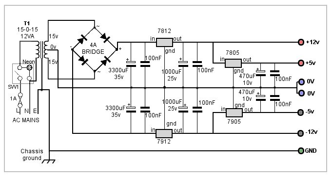
A dual voltage power supply schematic is a circuit design that allows for the provision of two different voltage levels from a single power source. This can be particularly useful in electronic devices and systems that require multiple voltage levels to operate efficiently. Circuit Diagram: Constructing Dual Power Supply Circuit: Step-I: Converting 220v AC into 12v AC using Step Down Transformer. The primary terminals of the centre tapped transformer is connected with household supply (220V ac, 50Hz) and output is taken from secondary terminals of the transformer.The centre tapped describes the voltage output of a center tapped transformer.

Dual Power Supply Circuit Diagram With Explanation
Complete Dual Power Supply Circuit using IC 741. The complete dual power supply circuit is shown in Figure 2 using 2N3055 transistors as the driver transistor. It divides the input voltage in half thanks to R1 and R2. Op-amp U1 replicates that voltage at the output side labelled "ground" by allowing Q1 or Q2 to conduct to the extent required.

This simple, low-cost solution is effective as long as the power loss and voltage drop across the resistors are acceptable. For higher power or better efficiency, the dual power supply circuit is necessary. Tapped Transformers. The simplest method of generating dual output voltages is to use a transformer with two taps on the output winding Here we design a dual power supply circuit by using a step-down transformer and linear voltage regulators. Mostly we see electronic circuits and applications operate in the DC voltage range that falls in 5, 12, and 15 Volts, therefore we are going to make three types of dual power supply circuits. All circuits have individual step-down Hope you are very well. Today i will show you how to create a dual power supply easily. The objective of this project is to convert 220V AC supply in to +12V and -12v DC supply, that is why it is named Dual Power Supply as we get positive and negative 12v power supply at the same time. Work: There are three step: 1.
What are the ways to make a dual power supply from a single voltage ... Circuit Diagram
For a quick and simple dual power supply, use two resistors in series connected in parallel with two capacitors. Connect the two ends to the battery or power source and BAM! You have a dual power supply. Typical values for bipolar converters like this are 100k-1M for the resistors and 47uf to 4700uf depending on the current draw of your circuit.