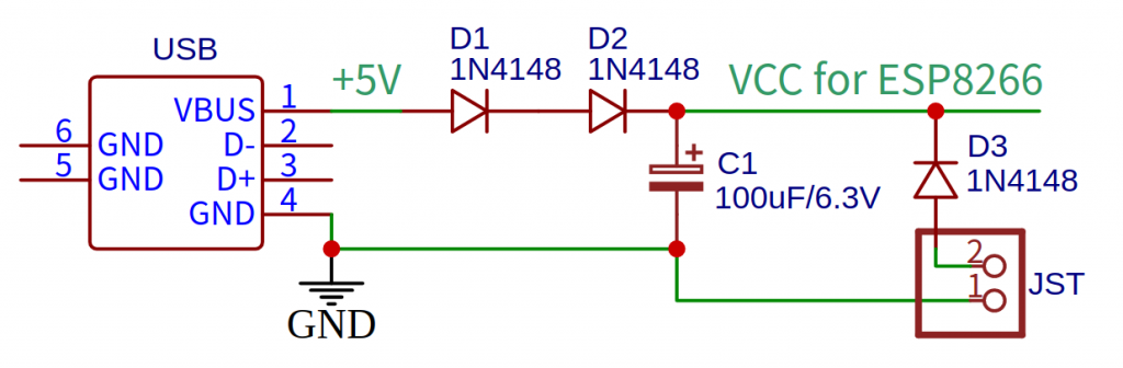
15 Esp8266 Circuit Diagram We have more than 200 ESP8266 NodeMCU Tutorials and project ideas as well as a Premium eBook Home Automation using ESP8266.Using the next quick links, you'll find all our ESP8266 Guides with easy to follow step-by-step instructions. Each tutorial includes circuit schematics, source code, images and videos. We have more than 150 ESP8266 NodeMCU Tutorials and project ideas as well as a Premium eBook Home Automation using ESP8266.Using the next quick links, you'll find all our ESP8266 Guides with easy to follow step-by-step instructions. Each tutorial includes circuit schematics, source code, images and videos. Circuit Design & Schematic. Here is the ESP8266 Schematic that can be powered by Battery. We are using the raw ESP8266 Chip, which is an ESP8266-12E/12F Chip. The board consists of low-power LDO, battery Management IC, USB for Battery Charging & switch for turning ON/OFF. The rest of the things is explained in detail.
This section covers electronics projects based on NodeMCU ESP8266 board. The NodeMCU is basically an open source firmware, and also commonly used term for the popular ESP8266 Development Board, which is a low cost, development board designed for IoT applications. Hammond's modern 1556 series enclosures are designed for circuit boards and The following is the list of all the components used to design the circuit of the ESP8266 WiFi Module PCB Board. ESP8266 WiFi Module (ESP-01) Female Headers (a few strips) Push Button; 1 KΩ Resistor (1/4 Watt) 2.2 KΩ Resistor (1/4 Watt) 100 nF Capacitor; Two Way Slide Switch; Circuit Design Circuit design Wifi Module ESP8266 created by LeXuanManh with Tinkercad. Circuit design Wifi Module ESP8266 created by LeXuanManh with Tinkercad. Tinker ; Gallery; Projects Design is visible in our gallery and to anyone with the link. Edited April 18, 2019 . Created April 18, 2019 . Report content .
DIY ESP8266 WiFi Module PCB: Design, Build, Program (Guide) Circuit Diagram
However, since this bare-bones board lacks the built-in circuitry needed to upload program sketches, I also had to design a separate "programmer" board. The Instructable describes how to make your own ESP8266 boards from scratch as well as how to wire a programmer that allows you to easily upload program sketches with the Arduino IDE (2.1).

Below are all the components integrated in designing the circuit of the ESP8266 PCB board: Female Headers (a few strips) Two Way Slide Switch; ESP8266 WiFi Module (ESP-01) Push Button; 2.2 KΩ Resistor (1/4 Watt) 1 KΩ Resistor (1/4 Watt) 100 nF Capacitor; Circuit Design. After you have designed your circuit diagram, you need a circuit design.
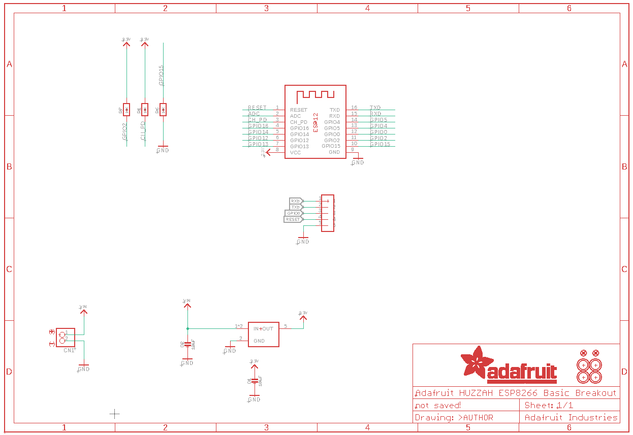
200+ ESP8266 NodeMCU Projects, Tutorials and Guides with Arduino IDE Circuit Diagram
ESP8266 is a low-cost Wi-Fi board, that you can easily wire to a microcontroller, and connect any project you build to the internet. The ESP8266 is actually an MCU in itself, but has very limited functions, therefore, it is recommended to connect it to another microcontroller such as Arduino using AT commands, either via Software Serial or Hardware Serial. As a concluding remark: ESP8266 has served me really well in the past several years. Although the lack of GPIO pins and the 'quirks' on various pins are major drawbacks, sometimes I feel these restrictions turn the circuit design into a 'constraint satisfaction' problem, which can be an interesting puzzle to solve than a total annoyance.